How to Make Lenticular Printing
Table of Contents
1. What is a Lenticular Lens?
2. Lenticular Print Markers
3. Lenticular Printing Procedure
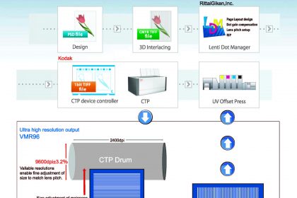
3-1: Lenticular Print Flow
3-2: Adjusting the Tilt of the Whole Lens 1
3-3: Adjusting the Tilt of the Whole Lens 2
3-4: Adjusting Color Registration
3-5: Confirming Pitch
3-6: Confirming Printed Matter
4. When Adjustments by Printing are Insufficient
4-1: Recreating Plate Data
4-2: Reexamining the Amount of Material (Lens Sheet)
4-3: Adjusting the Printer
1 What is a Lenticular Lens?
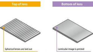
Semi-cylindrical lenses are arranged side by side on the top surface of the lenticular lens, and images are printed on the bottom surface. This makes it possible to view printed matter as a 3D image from the top.
Shape of the Lens
Top of lens
The top surface of the lens has semi-cylindrical convex lenses arranged side by side. When the image printed on the bottom surface is viewed through the lenses, the pattern changes according to the viewing angle, making it possible to express flat images three dimension-ally. Because a person’s left and right eyes view the image from different angles (parallax), the focal point of the convex lenses is different according to the viewing angle, and the im-age can change or can appear to have depth.
Bottom of lens
Printing is done on the bottom surface of the lenses. Regarding the images used for lenticular printing, at least two different images are divided linearly and placed alternatingly (interlaced image). To make a “3D” image, up to 20 images can be placed alternatingly to create an interlaced image. When viewed through the convex lenses, the left and right eyes view only a certain line of the image due to parallax, making images appear three dimensionally.
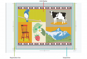
2 Lenticular Printing Markers
In order to perform lenticular printing properly, adjustments are made by viewing markers. With LentiDotManager, three types of markers are used.
Types of Markers
Striped line
Striped Lines are vertical lines that surround the four boarders of the printed matter. These are used for adjusting the tilt of the lens. When printing, you can select either Top-Bottom, Left-Right, or Top-Bottom-Left-Right from LentiDotManager by going to [Left-Right / Top-Bottom Stripe] in [Accessory Information Settings]. It is also possible to specify the width and height of the stripe. This is used for confirming the pitch.
AUA Marker
AUA Markers are markers that are printed at the top and bottom on the inside of the striped lines of the printed matter. When the pitch is correct, the letters “AUA” can be viewed clearly. When printing, you can select either Left, Right, or both from LentiDotManager by going to [AUA Mark] in [Accessory Information Settings]. It is also possible to specify the height of the mark.
Registration line
Registration lines are vertical lines outside striped lines. These are used for adjusting the tilt of the lens. Overall tilt adjustments are made using the striped lines, and detailed adjustments are made using the registration lines. For registration lines, you can select either Left, Right, or both from LentiDotManager by going to [Registration line] in [Accessory Information Settings]. Solid lines can be made dotted so that color registration can be matched more easily.

3 Procedure for Lenticular Printing
Now, let’s actually perform lenticular printing. Adjust the lens tilt and color registration to create a beautiful lenticular print.
3-1 Lenticular Print Flow
As with normal printing, use waste paper for lenticular printing, print onto the lens, and then perform tilt adjustment and color registration.

3-2 Adjusting the Tilt of the Whole Lens 1
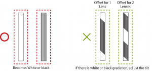
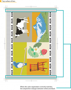
Adjust the tilt of the whole lens. Adjust the horizontal lines so that the striped lines become either completely white or black.
Adjustment Location
Tilt in front of the feeder portion
Adjustment Location
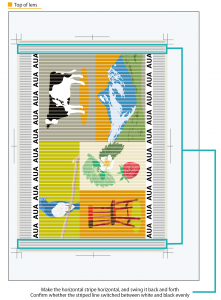
Lens Surface:Top surface
Marker:See the horizontal striped lines
Method:Adjust the horizontal lines so that the striped lines become either completely white or black.
To view the tilt in more detail
Rotate the lens sample 90 degrees to view the horizontal stripe horizontally. Swing it back and forth (vertically), and if the striped line switches between white and black evenly, it matches with the lens.
When streaking remains after adjusting the tilt
Depending on the type of CTP, there are cases where images are greatly tilted due to the spiral correction function. By making corrections and outputting the plate again, the initial tilt can be minimized (for more details, see 4-1-2 Correcting Registration Offset on the Plate).
3-3 Adjusting the Tilt of the Whole Lens 2
Now, let’s adjust the tilt of the whole lens more accurately.
Adjustment Location
Position and twist adjustment for each unit
Confirmation Method
Lens Surface:Bottom surface
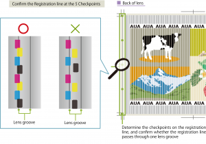
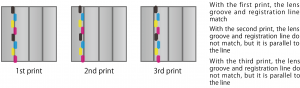
Marker:Determine the five checkpoints on the registration line, and see whether the registration line passes through one lens groove
Method:Place the registration line parallel to the lens groove Reconfirm the tilt adjustment of the whole lens (see 3-2 Adjusting the Tilt of the Whole Lens 1)
Note
The ends of each lens may not be aligned, so check multiple items that were printed together.
About Fluctuation with Each Lens
If it is diffi cult to make adjustments because the lens fl uctuation is too great, there may be a problem with the status of the lens sheet (For more details, see 4-2: Reexamining the Amount of Material (Lens Sheet))
3-4 Adjusting Color Registration
Adjust the color registration. Let’s confi rm the position and tilt of each color.
Adjustment Location
Position and twist adjustment for each unit
Confirmation Method
Lens Surface:Back surface
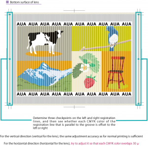
Marker:Determine three checkpoints on the left and right registration lines, and then see whether each CMYK color of the registration line that is parallel to the groove is off set to the left or right
Method:Make color registration adjustments so that each CMYK color of the registration line overlaps
Lens Surface:Top surface
Marker:See the horizontal striped lines
Method:Rotate the printed matter 90 degrees and swing it back and forth (vertical)
When it is difficult to see the registration line because it overlaps with the groove
It can be changed to a dotted line so that the registration line can be seen to overlap with two colors (For more details, see 4-1-4 Makes it easy to match color registration)
When the color registration adjustment range is exceeded
There are case where this is resolved by using the trapezoid correction function in LentiDotManager (For more details, see 4-1-2 Correcting Registration Offset on the Plate)
3-5 Confirming Pitch
See the AUA Mark and the striped lines at the top and bottom to confirm whether the lenticular print pitch is correct.
Confirmation Method
Lens Surface:Top surface
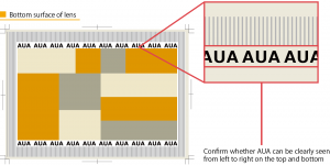
Marker:See the AUA Mark
Method:See “AUA” straight on and confirm whether all AUAs can be clearly seen
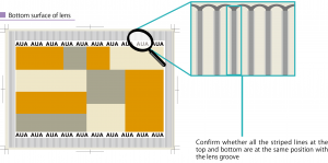
Lens Surface:Back surface
Marker:See the the striped lines at the top and bottom
Method:Confirm whether all striped lines are at the same position according to the lens groove
3-6 Confirming Printed Matter
Let’s confirm whether the lenticular print looks good by viewing actual printed matter.
Confirmation Method
Lens Surface:Top surface
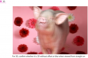
Marker:See the actual printed matter
Method Confirm whether each image can be seen in 3D when viewed from straight on
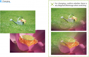
For changing, confirm whether switching is quick and complete
Colors do not match
There are cases when the desired color is not achieved even when the colors of the color balls match. This may be resolved by improving the color registration (see 3-4 Adjusting Color Registration)
Variation according to the position
3D is offset, afterimage remains for change switching
If it is crooked or partially switched, the image is tilted. Go back to 3-2 to 3-5 (see 3-2 Adjusting the Tilt of the Whole Lens 1) and reconfirm that color registration and pitch are correct.
When lenses are wavy
If lens curing (aging) is insufficient, the lens may become wavy (see 4-2: Reexamining the Amount of Material (Lens Sheet))
Streaking Appears
There are many possible causes for streaking with lenticular prints.
When streaking appears due to the spiral correction function
When the pitch is greatly off
When moiré appears

The corners of the image placed at the edge of the lens do not match
If the corner of the image is offset, this may be resolved by trapezoid correction (see 4-1-2 Correcting Registration Offset on the Plate)
The print results differ according to the lenses
Make sure that the direction of the lenses align and that the markers match with the gripper or pin. If the results differs after each print, the following are possible causes. It is also related to the storage status of the lens sheets, so it may be resolved by reexamining the lens sheets (see 4-2: Reexamining the Amount of Material (Lens Sheet))
When the lens direction is incorrect when feeding paper
When the lens quality is bad and edges do not align
4 When Adjustments by Printing are Insufficient
If adjustments by printing are insufficient, it is necessary to return to the previous process to make adjustments.
4-1 Recreating Plate Data
There are cases where plates are offset because the lens pitch does not match, and where color registration adjustments do not match. In such cases, print quality may be improved by making adjustments using LentiDotManager.
4-1-1 Measure the Pitch Accurately
If it is possible that the pitch does not match, place the unprinted lens on the CTP plate for pitch measurement to reconfirm the pitch. Input the correct pitch, and output the plate again. The CTP plate for pitch measurement can be used repeatedly. Use this to measure the pitch for the same type of lens.
Pitch Measurement Method
Output the chart to the CTP plate, place the lens on it, and then measure. When a lens is rotated by 90 degrees and used, the pitch changes according to the blanket thickness, etc. , so print on to the lens, and then measure the pitch. Because the influence from the blanket, etc. , is constant, it is possible to measure using the CTP plate by acquiring the factor.
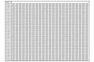
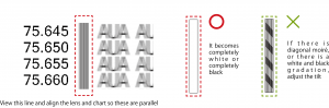
Overlap the lens and chart.
View the line between the number and AUA, and make the lens and chart parallel.
Stand directly in front of the AUA at the left-most column and move the lens so that all AUA in the column appear clearly (Figure 1).
[Figure 1]
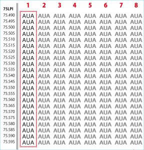
Without moving the lens and chart, move your body and stand directly in front of the next AUA column, and find the row where the AUA can be clearly seen. Do this in order from left to right starting from 1 (Figure 1) For a thin lens, when stretching to the right, the lens stretches, which changes the pitch. When a transparent sheet is placed, the bottom lens does not stretch, so hold the lens down from above the sheet and look while stretching to the right. When viewing AUA in order from the left, the AUA text begins to blur from the top or bottom of the chart (Figure 2), which means that the pitch for that row does not match.
[Figure 2]
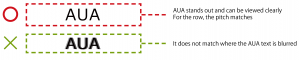
View these in order from left to right and record the number of the row where all AUA text can be seen clearly. This number is the Mechanical Lens Pitch.
![]()
4-1-2 Correcting Registration Offset on the Plate
When the lens and image registration do not match, or when each color registration does not match, it may be possible to improve it using fan-out correction (trapezoid correction).
* It is not necessary to change the fan-out correction each time. When type of lens is the same as the previous print, the same tendency will exist even if the pattern is different.
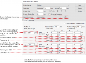
For [Position from Gripper] in [Top Trapezoid Correction Line], set the length from the edge of the plate on the gripper side to the top marker position, and for [Position from Gripper] in [Bottom Trapezoid Correction Line], set the length from the edge of the plate on the gripper back side to the bottom marker position.
4-1-3 Correcting the Tilt of an Image on a Plate
Depending on the type of CTP, there are cases where images are greatly tilted due to spiral correction function. By using both fan-out correction (trapezoid correction) and cocking correction (tilt correction), it is possible to make images nearly horizontal.
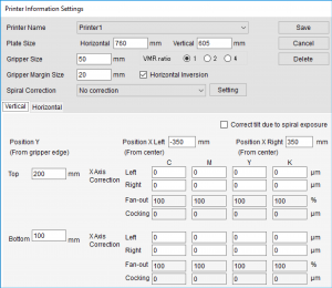
For more details about setting items, see 4-1-2 Correcting Registration Offset on the Plate
4-1-4 Makes it easy to match color registration
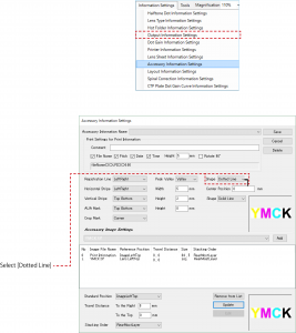
From the LentiDotManager [Accessory Information Settings], when Registration line is set to [Dotted Line], the lines are offset according to color, which makes it easy to match the color registration.
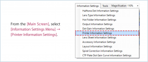
From the [Main Screen], select [Information Settings Menu]
→ [Accessory Information Settings].
From the Information Settings Screen, select [Registration line], and from [Shape]
select [Dotted Line].
4-2 Reexamining Materials (Lens Sheets)
There are cases where correct lenticular printing cannot be performed due to problems with the lens sheet. Reexamine the storage method for the lens sheets, etc.
Lens Aging
If lens sheet aging (curing) is insufficient, lenses can become wavy, making it impossible to make a good print. This can be checked by simply placing the lens on a flat surface.
Lens Selection
The lens pitch changes according to the lens thickness, maker, and lot production period. Even when the maker is the same, there is a difference in print ink application and pitch because the environment changes due to production location and season.
Reexamining Lens Storage Methods
Lenses can shrink or expand according to changes in season, time, day, etc. When lenses are stored by stacking, there is a difference in temperature between the edges and center portion of the lens, which creates distortion. Store lenses in a constant environment.
About Lens Edges
The edges of the lenses align differently according to the maker. The distance between lens ends and grooves differs according to each lens. When adjusting the overall tilt, in order to find the position that is best for printing, check several items that were printed at the same time (see 3-3 Adjusting the Tilt of the Whole Lens 2)
4-3 Adjusting the Printer
For lenticular prints, color registration adjustments are much more difficult than for normal printing.
In particular, have the maker make adjustments to the printer so that it meets “Fine halftone dot reproduce ” / “High color registration accuracy”.